

Views: 731 Author: Site Editor Publish Time: 2023-04-28 Origin: Site


Estun E21S controller is widely used in numerical control plate shears, such as hydraulic swing beam shears and hydraulic guillotine shears. Today we will share with you a detailed operating manual and instructions to help you better and more easily use this controller.

Functions of panel keys are described

is shown in


[Note] Parameter can only be set when Stop indicator is on.

Press ![]() , system will execute according to this program, as shown in
, system will execute according to this program, as shown in

On single-step program page, program back gauge position to 80.00mm, retract distance to 50mm, concession waiting time to 2s, and work piece to 10.


Step 1 Power on, the device enters to single-step parameter set up page automatically.
Step 2 Click![]() , switch to program manage page, as shown in
, switch to program manage page, as shown in

Step 3 Click ![]() , select program serial number, or input program number directly, such as input “1”.
, select program serial number, or input program number directly, such as input “1”.
Step 4 Click ![]() , enter multi-step program setting page, as shown in
, enter multi-step program setting page, as shown in

click ![]() , and the configuration takes effect.
, and the configuration takes effect.
Step 6 In completion of set up, click![]() , enter step parameter set page, as shown in
, enter step parameter set page, as shown in

Step 7 Click![]() ,select step parameter that needs to be set up, input program value,click
,select step parameter that needs to be set up, input program value,click![]() ,and the setup takes effect.
,and the setup takes effect.
Step 8 Click![]()
![]() to switch over between steps. If the current step is the first step, click
to switch over between steps. If the current step is the first step, click![]() to enter the last page of step parameter setting; if the current step is the last one, click
to enter the last page of step parameter setting; if the current step is the last one, click![]() to enter the first page of step parameter setting.
to enter the first page of step parameter setting.
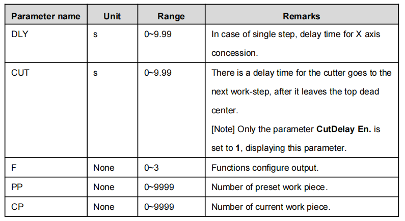
Multi-step parameter setting range is shown in


Step 9 Click![]() , system will operate according to this program, as shown in
, system will operate according to this program, as shown in

[Background] One work piece requires processing 50 as shown below;
Edit processing program of this work piece on No. 2 program.


[Note]
automatically. Restart directly will start another round of processing 50 work pieces.
User can setup the general parameters for the device, including the metric or imperial and the language.
Step 1 On program management page, click![]() ,click to enter programming constant page, as shown in below. On this page, programming constant can be set.
,click to enter programming constant page, as shown in below. On this page, programming constant can be set.


Step 2 Input password “1212”, click![]() , to enter Teach Page, as shown in
, to enter Teach Page, as shown in

Step 3 Step up parameter, parameter setup range is shown in

You can directly measure the positions of slider and back gauge. If the measurement is difficult, you can program and operate any one process, and then measure the accomplished workpiece.
Step 4 Click![]() , return to programming constant page.
, return to programming constant page.

Step 2 According to your actual requirement, following the above table to adjust the position of the axis.
A-axis and G-axis are controlled by the relays, press![]() to move them at low speed in increasing direction; press
to move them at low speed in increasing direction; press ![]() to move them at low speed in decreasing direction. Button
to move them at low speed in decreasing direction. Button![]() is of no effect on them.
is of no effect on them.
If the drive mode of X-axis is common motor:

<Note>: When the system is on run status, the operation of manual adjustment is just valid for the X-axis.
If the drive mode of the corresponding axis is frequency:

Step 3 Click ![]() return to single step parameter setting page.
return to single step parameter setting page.
Follow us as we update regularly for more exclusive information about sheet metal machinery. If you need to learn more and support please contact us to info@zfymachine.com or add WhatsAPP number: +86-156-555-77781, We are willing provide your free technical support.


